Editorial Solution
Let’s understand the logic gates,
Truth tables of all gates give us a clear idea of how gates work.
1.AND GATE ( 2-INPUT )
| INPUT A | INPUT B | OUTPUT |
| 0 | 0 | 0 |
| 0 | 1 | 0 |
| 1 | 0 | 0 |
| 1 | 1 | 1 |
2.OR GATE (2-INPUT)
| INPUT A | INPUT B | OUTPUT |
| 0 | 0 | 0 |
| 0 | 1 | 1 |
| 1 | 0 | 1 |
| 1 | 1 | 1 |
3.NOR GATE(2-INPUT)
| INPUT A | INPUT B | OUTPUT |
| 0 | 0 | 1 |
| 0 | 1 | 0 |
| 1 | 0 | 0 |
| 1 | 1 | 0 |
4.NAND GATE(2-INPUT)
| INPUT A | INPUT B | OUTPUT |
| 0 | 0 | 1 |
| 0 | 1 | 1 |
| 1 | 0 | 1 |
| 1 | 1 | 0 |
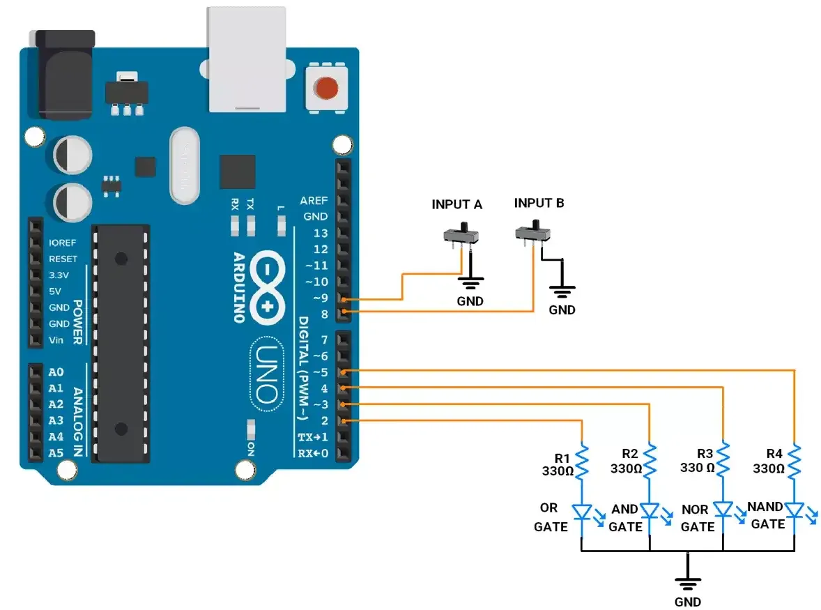
- So to implement gates we will use two slide switches and four LEDs. Each LED will show the output of the respective gate logic.
- We need to connect four LEDs to Arduino.
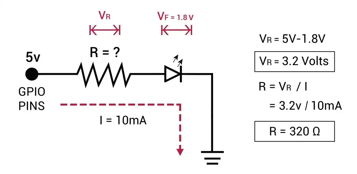
- We need a proper resistor for each LED to limit the current flowing through them to 10mA.
- As we can see below, 1.8v is the voltage drop across LED so the calculated resistor value is 320Ω. We can use a standard resistor near 320Ω which is 330Ω or 300Ω.

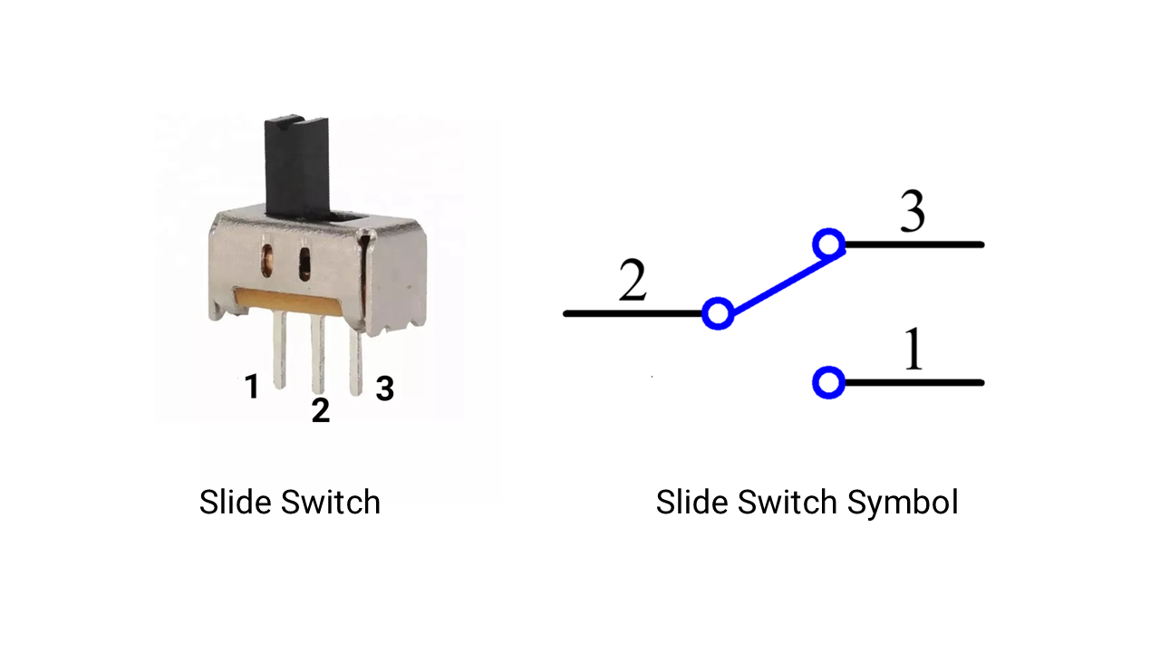
- The slide switch has three terminals. Terminal 2 (Middle) is common. We can connect the first terminal to VCC and the third terminal to GROUND or vice versa.
- When the switch is at the left position, terminals 1 and 2 make contact. When the switch slides to the right, terminals 2 and 3 make contact.

Circuit Connection
As the slide switch has three terminals,
- Terminal 1 (Ground): Connected to GND.
- Terminal 2 (Common): Connected to GPIO with internal pull-up enabled.
- Terminal 3: Not connected.
- When the common terminal is slide to the ground terminal, the GPIO reads logic 0.
- When the common terminal is slide to the unconnected terminal, the GPIO reads logic high due to the internal pull-up.

Code
- Based on the slide switch state, we simply have to implement logic gates.
- Here we don’t need to take care of debouncing, as it is only for a few milliseconds and won’t be visible in gate implementation or interfere with logic gate operation.
uint8_t gate_leds[4] = { 2, 3, 4, 5 };  // Pins for the LEDs representing logic gates (OR, AND, NOR, NAND)
uint8_t switch_pins[2] = { 8, 9 };      // Pins for the switches (inputs A and B)

uint8_t input_a = 1, input_b = 1;  // Variables to store the states of switches A and B

uint8_t ButtonState[2] = { HIGH, HIGH };      // Store the state of each button


void setup() {
  // Configure gate LED pins as outputs
  for (int i = 0; i < 4; i++) {
    pinMode(gate_leds[i], OUTPUT);
  }

  // Configure switch pins as inputs
  for (int i = 0; i < 2; i++) {
    pinMode(switch_pins[i], INPUT_PULLUP);
  }
}


void loop() {

    input_a = !digitalRead(switch_pins[1]);
    input_b = !digitalRead(switch_pins[0]);

  //LEDs update only when inputs A or B change.
  if ( input_a != ButtonState[1] || input_b != ButtonState[0]) {

    // Perform logic gate operations and update the corresponding LEDs state
    digitalWrite(gate_leds[0], input_a | input_b);     // OR operation
    digitalWrite(gate_leds[1], input_a & input_b);     // AND operation
    digitalWrite(gate_leds[2], !(input_a | input_b));  // NOR operation
    digitalWrite(gate_leds[3], !(input_a & input_b));  // NAND operation
  	ButtonState[1] = input_a;
  	ButtonState[0] = input_b;
  }
}
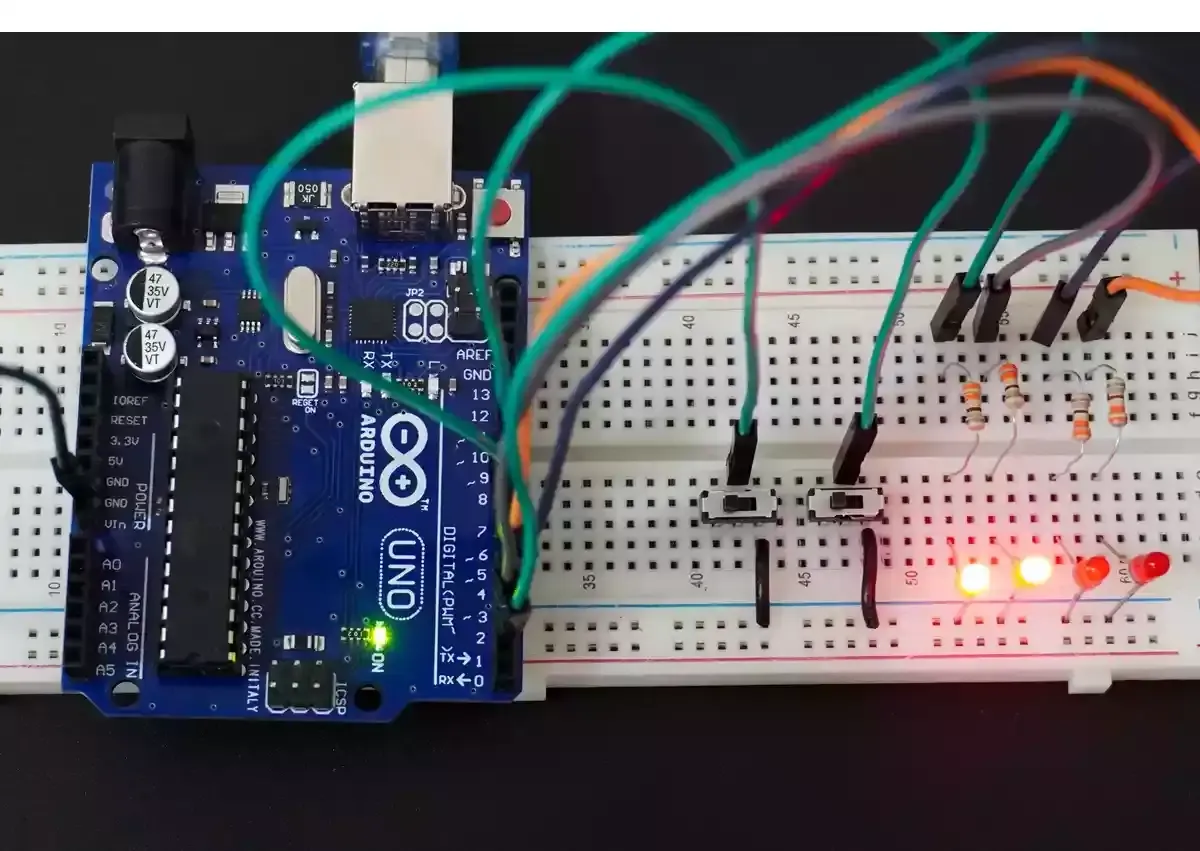
Output
- Logic gate implementation with 4 LEDs and 2 slide switch

Output Video