Editorial Solution
Let's first understand the 4-bit binary counter before implementing it.
- A 4-bit binary counter can count up to 2^4=16 states, ranging from 0x00 to 0x0F. The table below shows the counts for the counter.
| Counter Value in Decimal | Counter Value in Hexadecimal | Binary Count of Counter |
| 0 | 0X00 | 0000 |
| 1 | 0X01 | 0001 |
| 2 | 0X02 | 0010 |
| 3 | 0X03 | 0011 |
| 4 | 0X04 | 0100 |
| 5 | 0X05 | 0101 |
| 6 | 0X06 | 0110 |
| 7 | 0X07 | 0111 |
| 8 | 0X08 | 1000 |
| 9 | 0X09 | 1001 |
| 10 | 0x0A | 1010 |
| 11 | 0X0B | 1011 |
| 12 | 0X0C | 1100 |
| 13 | 0X0D | 1101 |
| 14 | 0X0E | 1110 |
| 15 | 0X0F | 1111 |
Let's connect hardware,
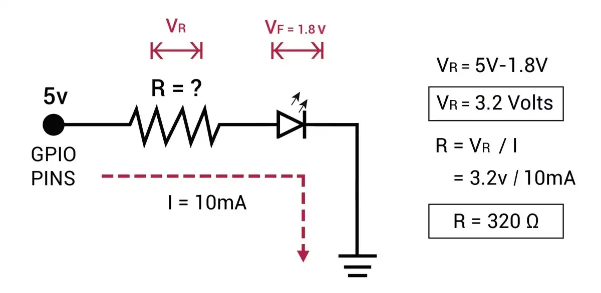
- We need to use a proper resistor for each LED to limit the current flowing through them to 10mA.
- As we can see below, the resistor value is 320Ω, So we can use a standard resistor near 320Ω which is 330Ω or 300Ω.

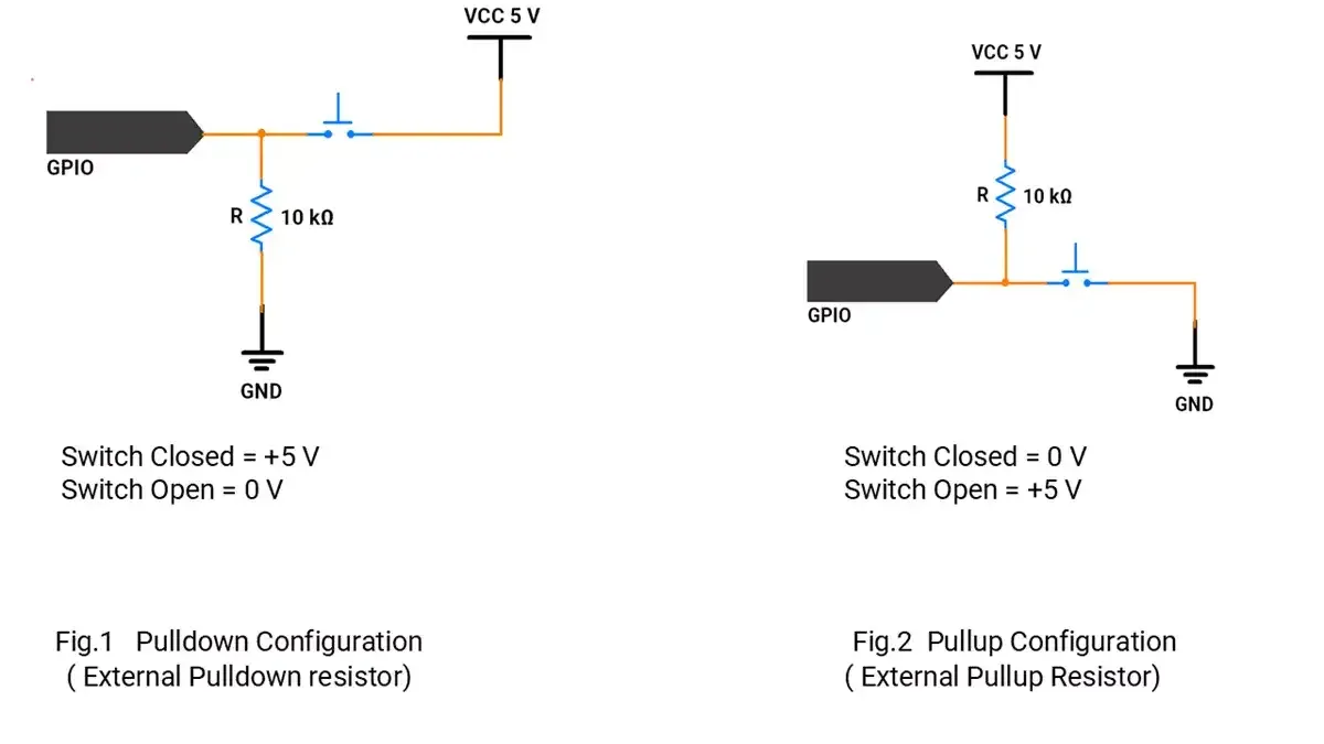
- We need to use two push-button switches to increment and decrement the count. While interfacing the switch, we need to carefully connect it, so that it will provide GPIO levels i.e. LOW and HIGH.
- To make sure HIGH and LOW voltage levels, we need to use PULLUP or PULLDOWN resistors.

- However, Arduino UNO GPIO has an internal PULLUP Resistor, which can be used for the Switch interface.
- To enable the internal pull-up resistor, configure the GPIO pin as follows: pinMode(switch_pin, INPUT_PULLUP);.
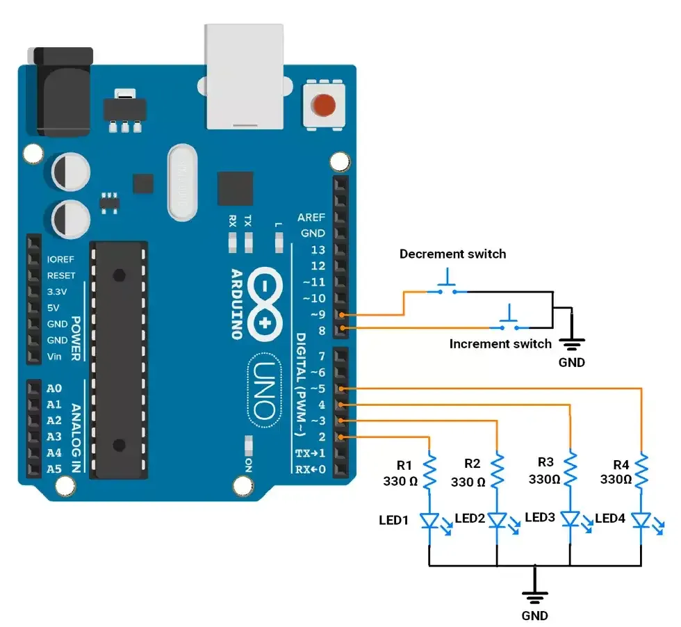
Circuit Diagram

Code
uint8_t ledPins[4] = {2, 3, 4, 5};            // LED pins connected to pins 2, 3, 4, 5
uint8_t switchPins[2] = {8, 9};               // Switch pins connected to pins 8, 9

uint8_t counter = 0;                          // Initial counter value


uint8_t debounceDelay = 50;                    // Debounce delay time (in milliseconds)
unsigned long lastDebounceTime[2] = {0, 0};   // Stores last debounce time for each switch
uint8_t lastButtonState[2] = {HIGH, HIGH};    // Stores the last state of each button
uint8_t ButtonState[2] = {HIGH, HIGH};        // Store the current state of each button

void setup() {

  for (int i = 0; i < 4; i++) {
    pinMode(ledPins[i], OUTPUT);             // Initialize LED pins as OUTPUT
  }

  for (int i = 0; i < 2; i++) {
    pinMode(switchPins[i], INPUT_PULLUP);    // Initialize switch pins as INPUT_PULLUP
  }

}

void loop() {
  // check increment switch
  if (isButtonPressed(0) && counter < 15) {
    counter++;
    updateLEDs();
  }

  // check decrement switch
  if (isButtonPressed(1) && counter > 0) {
    counter--;
    updateLEDs();
  }
}

// Check if a button has been pressed with debouncing
bool isButtonPressed(uint8_t switchIndex) {

  int reading = digitalRead(switchPins[switchIndex]);

  // If the button state has changed
  if (reading != lastButtonState[switchIndex]) {
    lastDebounceTime[switchIndex] = millis();                 // Reset debounce timer
  }
  lastButtonState[switchIndex] = reading;
  // If the state has remained stable for the debounce period(50 ms), consider it a valid press
  if ((millis() - lastDebounceTime[switchIndex]) > debounceDelay) {

    if (reading !=ButtonState[switchIndex] ) {
     ButtonState[switchIndex] = reading;
     // Checking if the button is pressed(LOW)
      if (ButtonState[switchIndex] == LOW) {
        return true;                             // Return true indicating a valid press
      }
    }
  }

  return false;                            // No valid press detected
}

// Update LEDs based on the current counter value
void updateLEDs() {
  for (int i = 0; i < 4; i++) {
    digitalWrite(ledPins[i], (counter >> i) & 1);
  }
}
Code explanation
bool isButtonPressed(uint8_t switchIndex);
- This function ensures proper button press detection by handling switch bounce, avoiding multiple triggers and noise spikes.
- Debounce Logic:
- If the button state changes, the debounce timer resets. It waits for the state to stay stable for a short time (Debounce Delay) to avoid noise. After the debounce period, if the button is pressed (state is LOW), it returns true.
void updateLEDs();
- This function updates the state of LEDs.
OUTPUT
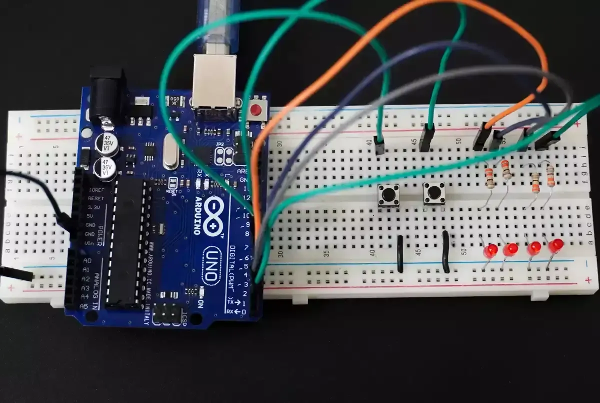
- 4-bit Binary Counter hardware setup

Output Video