Editorial Solution
Let's understand the RTC first,
- A Real-Time Clock (RTC) monitors time and maintains a calendar.
- We are going to use the DS1307 RTC module which works on I2C protocol at 100KHz speed with a 7-bit slave address of 0x68 typically.
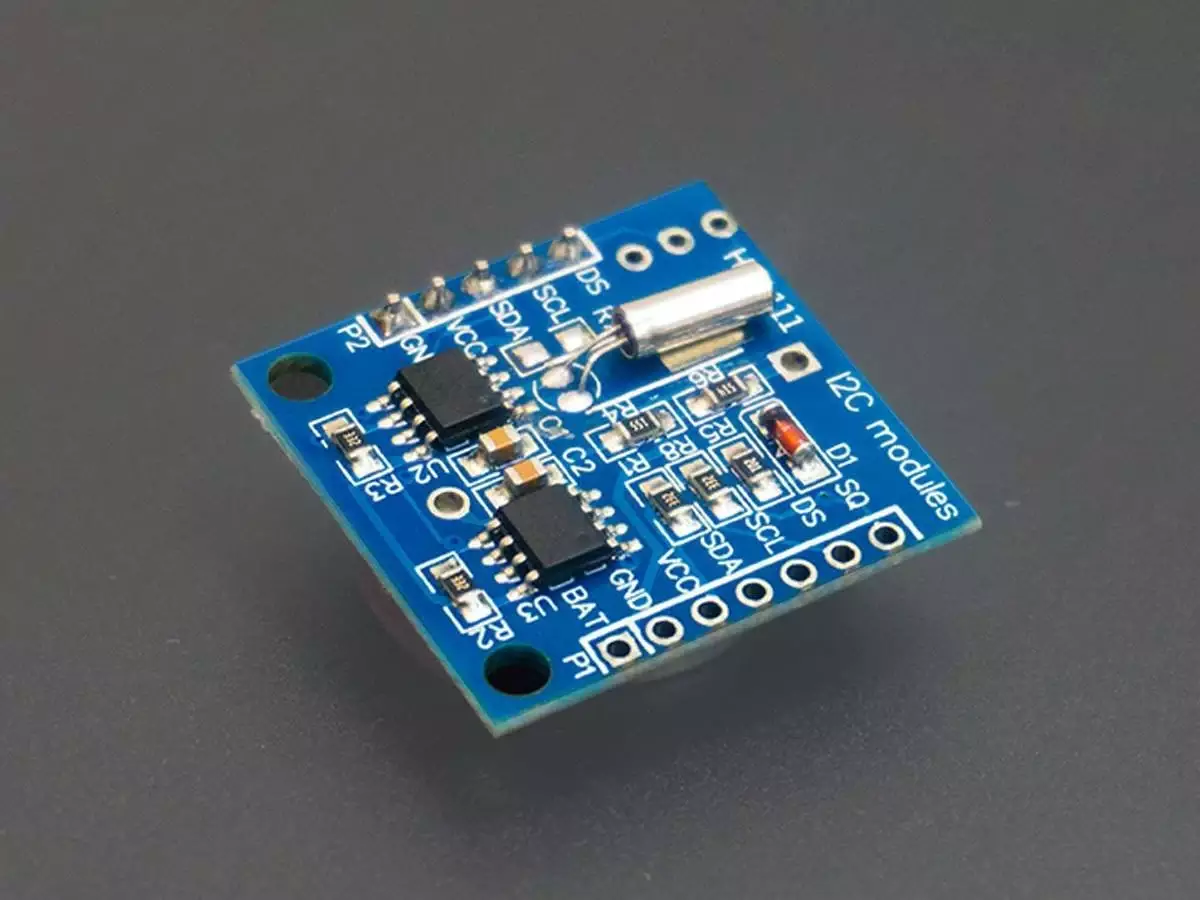
RTC Module(DS1307)
Pinout of DS1037 RTC module
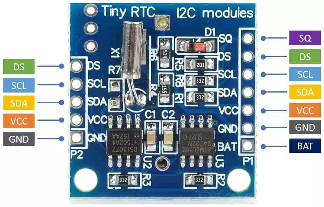
- The breakout board of this module has pins on both sides for ease of use. We will only use the 5 pins shown on the left side of the image.
- When powered ON for the first time, we might read random date and time values from the RTC module. So we must first program it with the current date and time.
- The data stored in the RTC module is in BCD format.
- Shown in the below image are the contents of the Timekeeper registers. There are eight registers in total. Once we set their values, they will keep updating themselves.

To know more about the DS1307 module please read EW Skill Attachment DS1307-3421066 datasheet
Now let's connect the hardware,
- Master and Slave Connection
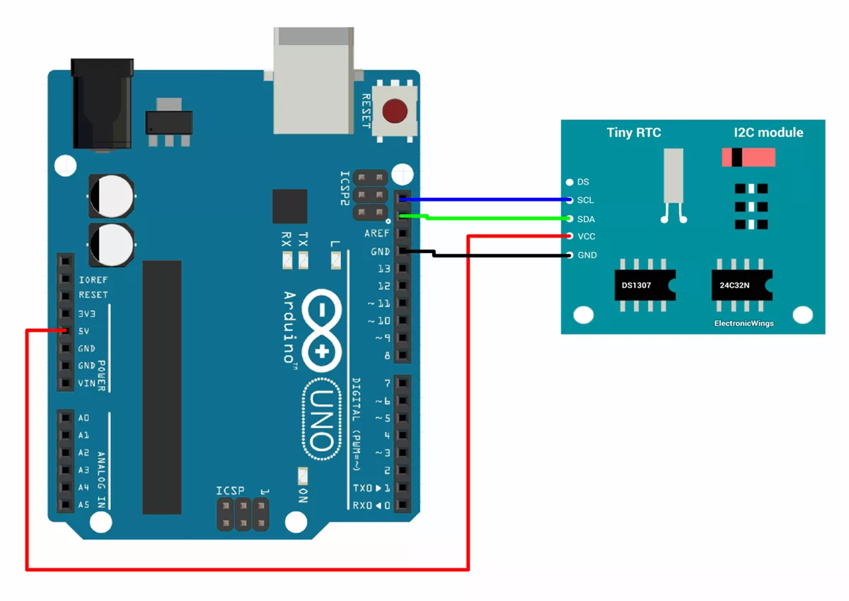
- Master Arduino’s SCL, SDA, and GND pins will be connected to the slave RTC modules’ SCL, SDA, and GND pins for I2C communication.
- The SCL and SDA lines should be pulled high for I2C communication. In our case, we will be using INTERNAL_PULLUP.
Circuit Diagram
Firmware
Wire.hlibrary is used for I2C communication between the slave(DS1307) and master(Arduino UNO).- To read the time value from the RTC module and to set the time initially we have created our user define function instead of using the ready-to-use library.
Master Arduino code
#include <Wire.h>

// DS1307 I2C address
#define rtc_addr 0x68

void setup() {
  Serial.begin(115200);
  Wire.begin();
  rtcStart();  // start RTC module
}

void loop() {
  int hour, minute, second;
  String isAMPM;

  readTime(hour, minute, second, isAMPM);

  // Display the time on the Serial Monitor (12 hour format)
  Serial.print("Time: ");
  Serial.print(hour);
  Serial.print(":");
  Serial.print(minute);
  Serial.print(":");
  Serial.print(second);
  Serial.print(" ");
  Serial.println(isAMPM);
  delay(1000);

}


// Function to convert BCD to decimal
int bcdToDec(byte val) {
  return ((val / 16) * 10) + (val % 16);
}


// Function to convert decimal to BCD
byte decToBcd(int val) {
  return (val / 10 * 16) + (val % 10);
}


// Function to read the time from the DS1307
void readTime(int &hour, int &minute, int &second, String &isAMPM) {
  Wire.beginTransmission(rtc_addr);
  Wire.write(0x00);                       // Start at the 0th register (seconds)
  Wire.endTransmission();
  Wire.requestFrom(rtc_addr, 3);          // Request 3 bytes (second, minute, hour)
  second = bcdToDec(Wire.read() & 0x7F);  // Mask the 7th bit (CH bit)
  minute = bcdToDec(Wire.read());
  byte rawHour = Wire.read();             // Read the raw hour


  bool isPM = rawHour & 0x20;             // Read the 5th bit and mask other bits
  hour = bcdToDec(rawHour & 0x3F);        // mask two msb bits read the hour value

  // Convert to 12-hour format

  if (hour == 0) {  // Midnight case
    hour = 12;      // 12 AM
    isAMPM = "AM";
  } else if (hour > 12) {  // PM case (1-11 PM)
    hour -= 12;
    isAMPM = "PM";
  } else if (hour == 12) {  // Noon case (12 PM)
    isAMPM = "PM";
  } else {  // AM case (1-11 AM)
    isAMPM = "AM";
  }
}


void rtcStart(void)
{
  uint8_t sec;

  //get second and CH bit
  Wire.beginTransmission(rtc_addr);
  Wire.write(byte(0x00));
  Wire.endTransmission();
  Wire.requestFrom(rtc_addr, 1);
  sec = Wire.read();
  Wire.read();

  //set second and clear CH bit
  Wire.beginTransmission(rtc_addr);
  Wire.write(byte(0x00));
  Wire.write(sec & 0x7F);
  Wire.endTransmission();
  Serial.println("RTC Start");
}
Understand the code
void readTime(int &hour, int &minute, int &second, String &period);Function used to read the time from the DS1307 RTC module. We first send the register address, and then read the content of each register one by one.void rtcStart(void);It is used to start the RTC module. The CH (Clock Halt) bit of the 0x00h address register is cleared to enable the RTC oscillator.
Code to set RTC time initially
- We use the
setTime();function invoid setup()to initially set the time in the RTC. uint8_t rtcResponding();Check whether the device is present in the network or not.- This code is uploaded once in Arduino UNO to configure the RTC time.
- After the time is set, we will upload the Arduino master code in Arduino UNO.
#include <Wire.h>

// DS1307 I2C address
#define rtc_addr 0x68
uint8_t error_code;

void setup() {
  Wire.begin();
  Serial.begin(115200);
  uint8_t rtc_response;
  Serial.print("Device scanning...");
  while(rtc_response = rtcResponding()){
    Serial.print(".");
    delay(100);
  }
    setTime(15, 47, 0);  // Set RTC time (min= 0-59, sec= 0-59, Hours = 00 to 23)
    if (!error_code) {
      Serial.println("\nRTC device found");
      Serial.println("Time set successfully");
    } else {
      Serial.println("Time is not Set...");
    }
  }


void loop() {
}

// Function to convert BCD to decimal
int bcdToDec(byte val) {
  return ((val / 16) * 10) + (val % 16);
}


// Function to convert decimal to BCD
byte decToBcd(int val) {
  return (val / 10 * 16) + (val % 10);
}

// Function to set the time on the RTC DS1307
void setTime(int hour, int minute, int second) {
  Wire.beginTransmission(rtc_addr);  // communication start
  Wire.write(0x00);                  // Start at the 0th register (seconds)
  Wire.write(decToBcd(second));      // Set seconds
  Wire.write(decToBcd(minute));      // Set minutes
  Wire.write(decToBcd(hour));        // Set hours
  error_code = Wire.endTransmission(); // transfer data and end communication
}

// Checck RTC slave device present or not
uint8_t rtcResponding() {
  Wire.beginTransmission(rtc_addr);
  uint8_t response = Wire.endTransmission();
  return response;
  }
OUTPUT
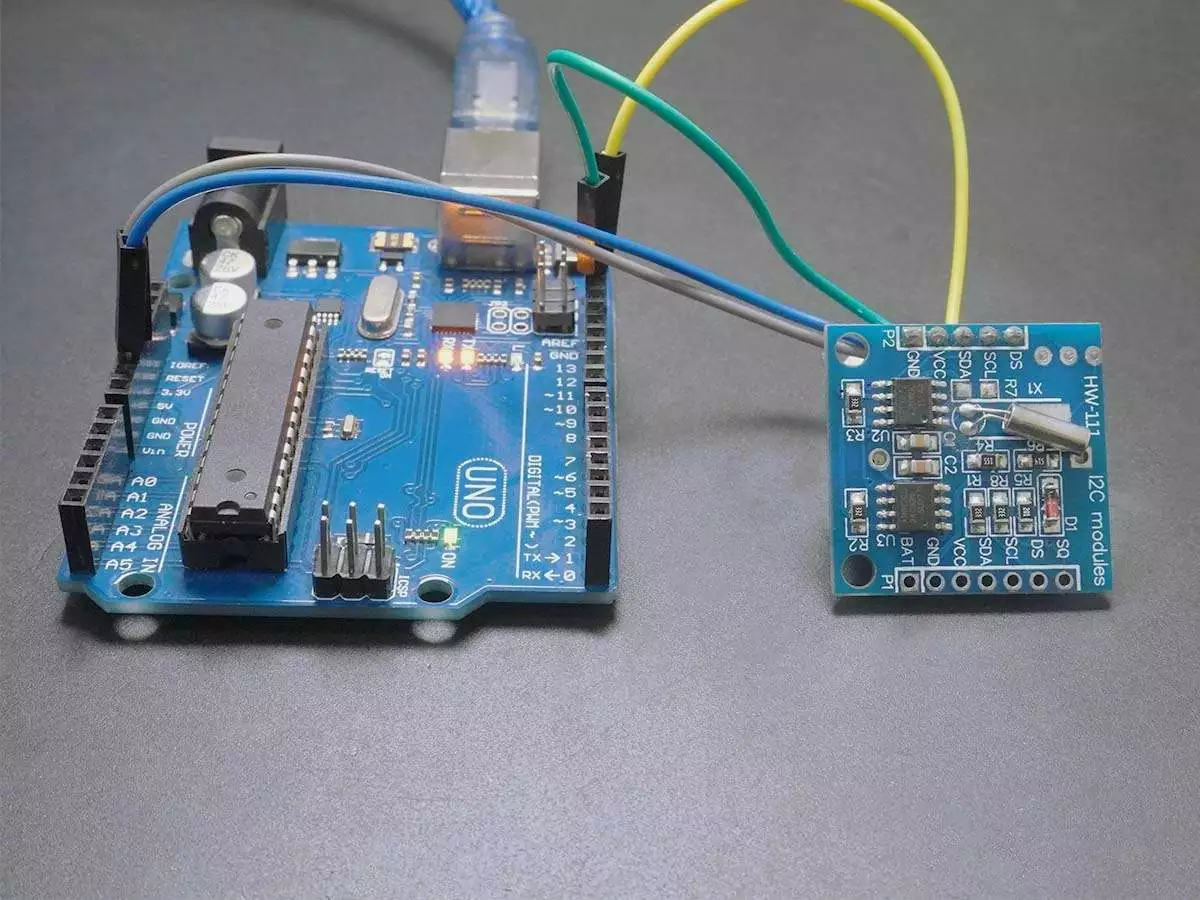
HARDWARE SETUP
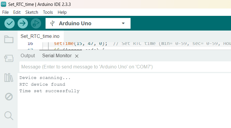
OUTPUT Screen-shot
RTC Time Set
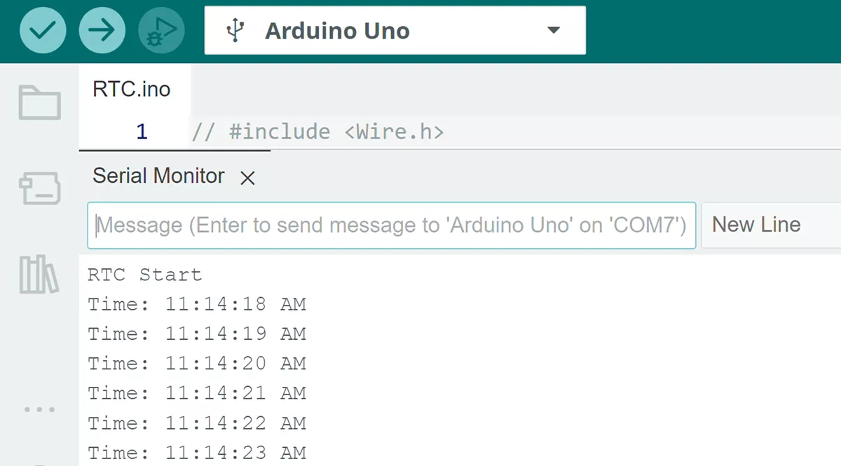
RTC Time Read
VIDEO
As we can see in video, the time read from RTC and printed on a serial monitor.