Editorial Solution
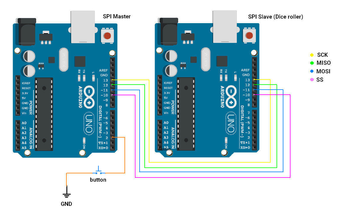
For this task, we will need 2 Arduino’s.
- Master Arduino to read Random numbers over SPI, if the button is pressed.
- Slave Arduino will be a dice roller device.
In case you don’t have a spare Arduino you can use any other microcontroller with SPI communication capability.
Modes of SPI communication in Arduino UNO:
SPI modes are determined by two key parameters: Clock Polarity (CPOL) and Clock Phase (CPHA). Together, these define the timing relationship between the clock signal and the data transmission.
| Mode | Clock Polarity (CPOL) | Clock Phase (CPHA) | Output Edge | Data Capture |
| SPI_MODE0 | 0 | 0 | Falling | Rising |
| SPI_MODE1 | 0 | 1 | Rising | Falling |
| SPI_MODE2 | 1 | 0 | Rising | Falling |
| SPI_MODE3 | 1 | 1 | Falling | Rising |
The dice roller device uses mode 2. In Arduino, we can use SPI.setDataMode(SPI_MODE); function to select the SPI mode.
Circuit Diagram

In the slave SPI device, we will upload the code below (also given in the Problem statement)
Code (SPI slave - Dice roller)
#include <SPI.h>

void setup() {
  pinMode(MISO, OUTPUT);  // Set MISO as OUTPUT to send data to the master

  // Enable SPI in slave mode
  SPCR |= _BV(SPE);

  // Send SPI data in mode 2
  SPI.setDataMode(SPI_MODE2);

  // Attach SPI interrupt
  SPI.attachInterrupt();

  //Generate random number and store it to transmit during SPI communication.
  SPDR = random(1, 7);
}

ISR(SPI_STC_vect) {

  //Generate a random number and send it.
  SPDR = random(1, 7);
}

void loop() {
}
Code explanation
SPCR |= _BV(SPE): This statement configures Arduino as an SPI slave.SPI.setDataMode(SPI_MODE2): configures SPI communication to use MODE 2.SPI.attachInterrupt(): This statement enables SPI interrupt & we can also assign ISR in the function ISR(SPI_STC_vect).SPDR = random(1, 7): Generate a random number between 1 and 6. Which is written to the SPDR register. The data in the SPDR register will be transmitted over the SPI bus.
The code of Master Arduino will have the flow as follows:
- Configure SPI to communicate in MODE 2.
- Detect if the button is pressed by the user.
- Read the random number received from the Dice roller slave device and print it on the Serial monitor ( start again at point 2 ).
Code (SPI Master)
#include <SPI.h>  // Include SPI library for communication
#define buttonPin 2
/* all the variables declared below are for button Debouncing detection purposes */
unsigned long debounce_duration = 50;  // Minimum time to debounce button (in milliseconds)
int previous_button_state = HIGH;      // Previous state of the button
int current_button_state = HIGH;       // Current state of the button
unsigned long last_debounce_time = 0;  // Time when button state last changed
unsigned long press_start_time;        // Time when button press starts
unsigned long release_time;            // Duration of the button press

void setup() {
  Serial.begin(115200);
  // Initialize button GPIO
  pinMode(buttonPin, INPUT_PULLUP);
  // Start SPI communication as master
  SPI.begin();
  SPI.setDataMode(SPI_MODE2);
  // Set SPI clock divider to 4 (4 MHz SPI clock)
  SPI.setClockDivider(SPI_CLOCK_DIV4);
  // Set SS (Slave Select) pin to HIGH to prevent the master from selecting the slave initially
  digitalWrite(SS, HIGH);
  Serial.println("Click button to :dice: Roll a Dice : ");
}

void loop() {
  if (debounced_button_press_check(buttonPin, LOW)) {
    // byte variable to store random-number
    byte Mastereceive;
    // Begin communication with the slave by pulling SS pin LOW
    digitalWrite(SS, LOW);
    // Send x to the slave and receive the response from the slave
    Mastereceive = SPI.transfer(0);
    // check if the slave (dice roller) has returned valid value
    if (Mastereceive > 0 && Mastereceive < 7) {
      Serial.print("You :dice: rolled a ");
      Serial.print(Mastereceive);
      Serial.println(" !");
    } else {
      Serial.println("Dice roller not working. Retry after some time and please check circuit connections ");
    }
    // End communication with slave by pulling SS HIGH
    digitalWrite(SS, HIGH);
  }
}

//Checks for a debounced button press and returns true if detected, false otherwise.
bool debounced_button_press_check(int pin, bool expected_state) {
  int button_reading = digitalRead(pin);
  // If the button state has changed, reset the debounce timer
  if (button_reading != previous_button_state) {
    last_debounce_time = millis();
  }
  previous_button_state = button_reading;
  // If the state has remained stable beyond the debounce duration, consider it valid
  if ((millis() - last_debounce_time) > debounce_duration) {
    if (button_reading != current_button_state) {
      current_button_state = button_reading;
      if (current_button_state == expected_state) {
        return true;  // Return true if the desired state is detected
      }
    }
  }
  return false;  // Return false if no valid press is detected
}
Code explanation
SPI.setDataMode(SPI_MODE2): configures SPI communication to use MODE 2.SPI.setClockDivider(SPI_CLOCK_DIV4): This statement configures SPI communication to communicate at 4 MHz. (16 MHz / 4).digitalWrite(SS, HIGH): In SPI, ideally when no communication is taking place, the SS line is HIGH. But when communication is ongoing SS line should be LOW.SPI.transfer(data): This function transmits the data and returns the received data over the SPI bus.if (Mastereceive > 0 && Mastereceive < 7): Checks if the received data is in the valid range. If Dice Roller (slave) is not initialized it returns garbage value. Thus, this check is important.debounced_button_press_check(buttonPin, LOW): This function returns True if the buttonPin has transitioned from HIGH to LOW (i.e. button is pressed).
When the button is pressed, we are reading a random number & printing it on the Serial monitor.
Output
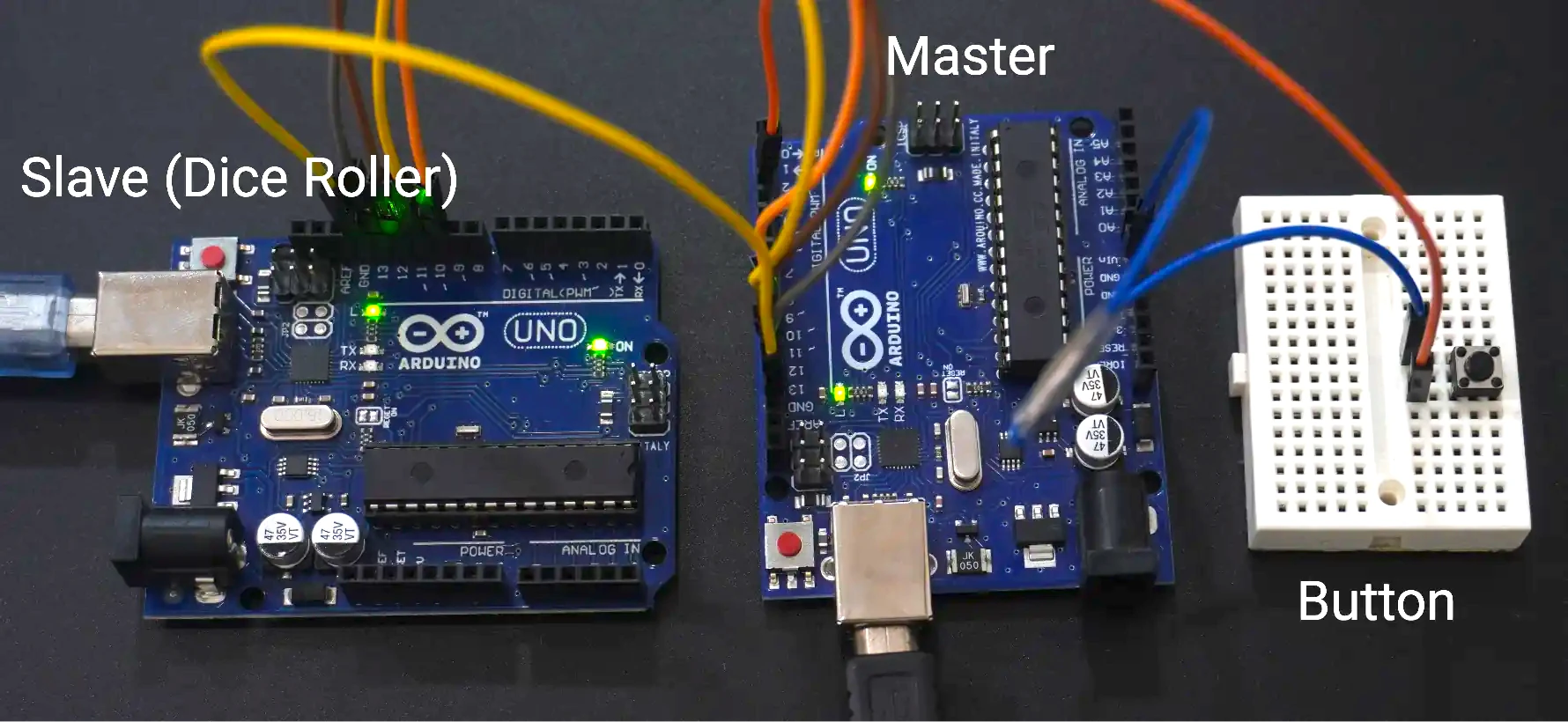
The setup photo

Output Video