Editorial Solution
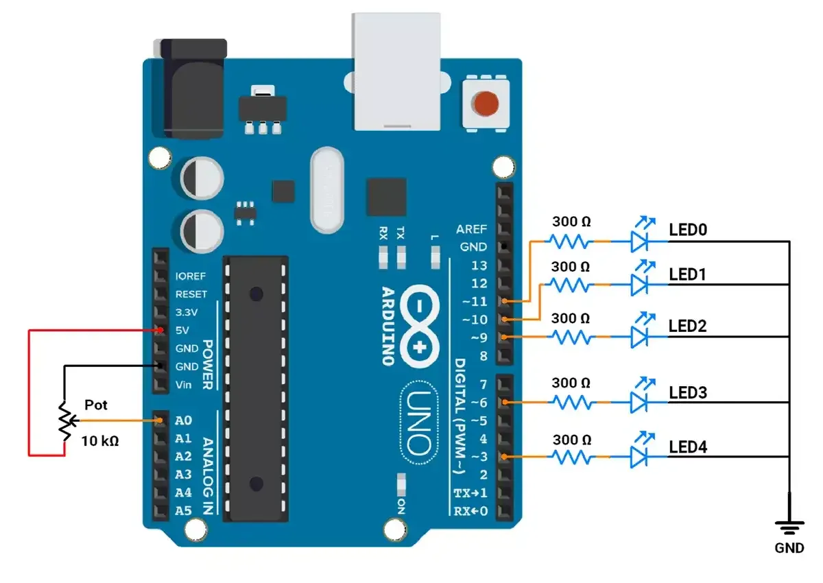
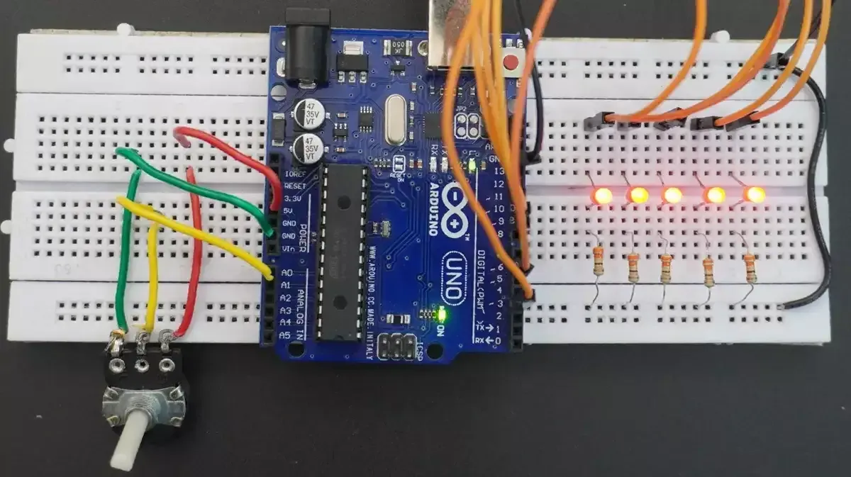
First of all, let's do the hardware connection,
We need to connect the potentiometer to the Arduino ADC. We can use any of the potentiometers with values between 1kΩ and 10kΩ.
Similarly, we can connect the 5 LEDs properly to any 5 PWM pins.
Considering LED drop voltage of ~2 volts and 10mA current, we can use a resistor with a value,
R = (Vcc - Vled) / I
= (5-2)/0.01
= 300 Ω
Circuit connection

Firmware
After analyzing the task requirement as shown in the GIF.
Mapping ADC to PWM:
The ADC provides values ranging from 0 to 1023.
To control the LED brightness using PWM (which ranges from 0 to 255), the ADC values are converted using the map() function.
Let’s Consider, that the potentiometer is at 0%, i.e. ADC output is 0. In this case,
| LED | Brightness Level |
| LED0 | 0% |
| LED1 | 25% |
| LED2 | 50% |
| LED3 | 75% |
| LED4 | 100% |
Similarly, when the potentiometer goes to 100% i.e. ADC value to 1023, the brightness levels will get reversed.
Considering the above case,
Mapping value Linearly for PWM:
- LED0: Brightness (PWM Value) increases from 0 to 255 linearly with ADC values 0 to 1023.
- LED1: Brightness (PWM Value) increases from 64 to 191 linearly with ADC values 0 to 1023.
- LED2: Brightness (PWM Value) remains constant at 127 (50%).
- LED3: Brightness (PWM Value) decreases from 191 to 64 linearly with ADC values 0 to 1023.
- LED4: Brightness (PWM Value) decreases from 255 to 0 linearly with ADC values 0 to 1023.
However, with this mapping of LEDs that aren't showing proper brightness level shift as expected, we made a few adjustments and made it more dynamic for proper visible effect.
(Note: Brightness levels/ intensity behavior of LEDs varies based on specifications, different LEDs have different behavior. The LEDs we are using have similar brightness levels visible for PWM values in the upper range (e.g.150 to 255) )
Mapping value more dynamically to adjust for Better Visibility:
- LED0: Brightness (PWM Value) increases from 0 to 255 linearly with ADC values 0 to 1023.
- LED1: Brightness (PWM Value) increases from 10 to 245 linearly with ADC values 0 to 1023.
- LED2: Brightness (PWM Value)
- Increases from 30 to 225 as ADC value goes from 0 to 511.
- Decreases from 225 to 30 as ADC value goes from 512 to 1023.
- LED3: Brightness (PWM Value) decreases from 245 to 10 linearly with ADC values 0 to 1023.
- LED4: Brightness (PWM Value) decreases from 255 to 0 linearly with ADC values 0 to 1023.
Example Code with Linear Mapping
const int ledPins[] = {11, 10, 9, 6, 3};  // PWM pins for LEDs
int potValue = 0;	// Variable to store potentiometer value

void setup() {
  // Initialize all LED pins as outputs
  for (int i = 0; i < 5; i++) {
    pinMode(ledPins[i], OUTPUT);
  }
}

void loop() {
  // Read the potentiometer value (range: 0–1023) connected to Pin A0
  potValue = analogRead(A0);

  // Adjust the brightness of LEDs based on the potentiometer value
  setLEDBrightness(potValue);
}

  // Function to calculate and set LED brightness levels based on potentiometer input
void setLEDBrightness(int potValue) {
  // Map the potentiometer value (0–1023) to PWM brightness range (0–255)
  // Brightness levels are adjusted to create a gradient effect across LEDs
  int brightnessLed0 = map(potValue, 0, 1023, 0, 255);
  int brightnessLed1 = map(potValue, 0, 1023, 64, 191);
  int brightnessLed2 = 127;
  int brightnessLed3 = map(potValue, 0, 1023, 191, 64);
  int brightnessLed4 = map(potValue, 0, 1023, 255, 0);

  /**
   * When the potentiometer is at 100% position, the ADC value fluctuates between 1023 and 1022.
   * This causes the PWM value to alternate between 255 and 254, leading to noticeable LED flickering.
   * To eliminate the flickering, any brightness value below 2 is set to 0,
   * ensuring the LED turns off completely in such cases.
   */
  if (brightnessLed4 < 2) {
    brightnessLed4 = 0;
  }

  // Set PWM values to adjust brightness for each LED
  analogWrite(ledPins[0], brightnessLed0);
  analogWrite(ledPins[1], brightnessLed1);
  analogWrite(ledPins[2], brightnessLed2);
  analogWrite(ledPins[3], brightnessLed3);
  analogWrite(ledPins[4], brightnessLed4);

  delay(10);	// Short delay for smooth transitions

}
Code with more Dynamic mapping for proper visibility
const int ledPins[] = {11, 10, 9, 6, 3};  // Array of LED pins (PWM-enabled pins)
int potValue = 0;	// Variable to store the potentiometer reading

void setup() {
  // Configure each LED pin as an output
  for (int i = 0; i < 5; i++) {
    pinMode(ledPins[i], OUTPUT);
  }
}

void loop() {
  // Read the analog input from the potentiometer connected to pin A0 (range: 0–1023)
  potValue = analogRead(A0);

  // Set the brightness levels of LEDs based on the potentiometer value
  setLEDBrightness(potValue);

  // Short delay for smoother brightness transitions
  delay(10);
}

/**
 * Function to calculate and set the brightness levels of LEDs
 * based on the potentiometer input.
 * @param potValue - Potentiometer ADC reading (0–1023)
 */
void setLEDBrightness(int potValue) {
  // Map the potentiometer value to brightness levels for each LED
  int brightnessLed0 = map(potValue, 0, 1023, 0, 255);
  int brightnessLed1 = map(potValue, 0, 1023, 10, 245);
  int brightnessLed3 = map(potValue, 0, 1023, 245, 10);
  int brightnessLed4 = map(potValue, 0, 1023, 255, 0);
  int brightnessLed2;  // LED 2: Dynamic range with midpoint behavior

  /**
   * When the potentiometer is at 100% position, the ADC value fluctuates between 1023 and 1022.
   * This causes the PWM value to alternate between 255 and 254, leading to noticeable LED flickering.
   * To eliminate the flickering, any brightness value below 2 is set to 0,
   * ensuring the LED turns off completely in such cases.
   */
  if (brightnessLed4 < 2) {
    brightnessLed4 = 0;
  }

  // Calculate brightness for the middle LED (LED 2)
  if (potValue < 512) {

    // If potentiometer is below the midpoint, brightness increases (30–225)
    brightnessLed2 = map(potValue, 0, 511, 30, 225);
  } else {
    // If potentiometer is above the midpoint, brightness decreases (225–30)
    brightnessLed2 = map(potValue, 512, 1023, 225, 30);
  }

  // Apply calculated brightness to each LED
  analogWrite(ledPins[0], brightnessLed0);
  analogWrite(ledPins[1], brightnessLed1);
  analogWrite(ledPins[2], brightnessLed2);
  analogWrite(ledPins[3], brightnessLed3);
  analogWrite(ledPins[4], brightnessLed4);

  delay(10);	// Short delay for smooth transitions
}
Code Explanation
Brightness for LEDs:
- LED 0: Linear increase from 0 to 255.
- LED 1: Limited range increase from 10 to 245.
- LED 2: Dynamic increase from 30 to 225 (0–511) and decrease from 225 to 30 (512–1023).
- LED 3: Reverse of LED 1, decreases from 245 to 10.
- LED 4: Linear decrease from 255 to 0.
- In the next cycle, the above conditions will be reversed.
Map Function:
- The
map()function has a limitation: it works only with integer numbers.- For example, if the expected mapped value is 1.999, the function will return 1 instead of a precise decimal value.
- When the potentiometer is set to 100%, the ADC value fluctuates between 1022 and 1023.
- This fluctuation causes the PWM value to vary between 0 and 1, which leads to noticeable LED flickering.
- To resolve this issue:
- Add a condition to check the PWM value.
- If the PWM value is below 2, set it to 0.
- This arrangement ensures smooth and stable LED operation, preventing Flickering.
Output

Output Video