Editorial Solution
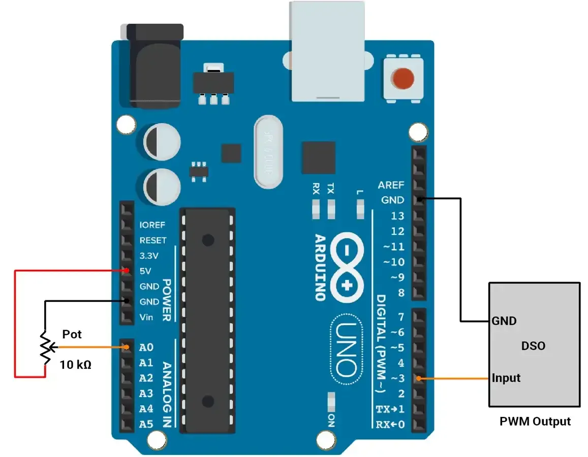
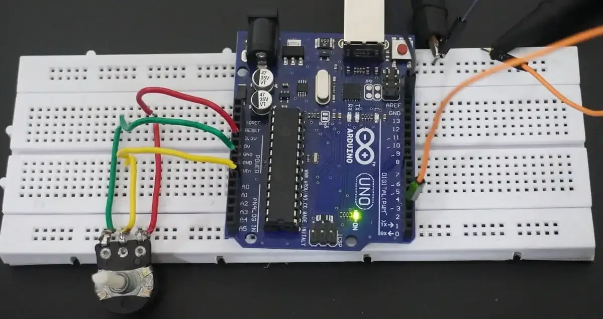
First of all, let's do the hardware connection,
- We need to connect the potentiometer to the Arduino's ADC. We can use any of the potentiometers with values between 1kΩ and 10kΩ.
- We can use any of the available PWM channels, and for this implementation, we will use PWM pin 3.
Circuit connection

Firmware
To control the duty cycle of PWM:
- ADC values range from 0 to 1023 and PWM values range from 0 to 255
- ADC and PWM values are mapped using the
map()function. - Change the duty cycle of PWM using the OCR2B register.
Default PWM Frequency:
- On the Arduino Uno, PWM pin 3 is controlled by Timer2.
- The default PWM frequency for pin 3 is 490 Hz (when using
analogWrite()).
How to Change PWM Frequency on Arduino UNO:
To generate a PWM signal between 5 kHz and 10 kHz on Pin 3 using Timer2,
Formula:
PWM Frequency = Clock Frequency / ( Prescaler * 256 )
Where, Clock Frequency = 16 MHz (Arduino clock speed).
Prescaler Calculation:
Prescaler = Clock Frequency / ( PWM Frequency * 256 )
- For 5 kHz: Prescaler ≈ 12.5
- For 10 kHz: Prescaler ≈ 6.25
- Closest Prescaler: 8
Resulting Frequency:
With prescaler = 8.
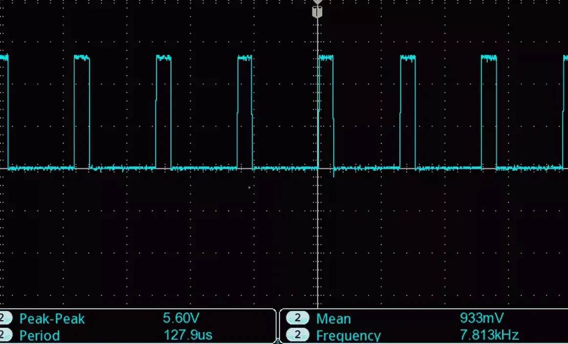
PWM Frequency = 16000000/ ( 8 * 256) = ~ 7.8 kHz
Timer2 Configuration:
- Set Fast PWM Mode: WGM20=1, WGM21=1.
- Set Non-Inverted Output: COM2B1=1.
- Set Prescaler to 8.
TCCR2A = (1 << WGM20) | (1 << WGM21) | (1 << COM2B1); // Fast PWM, non-inverted
TCCR2B = (TCCR2B & 0b11111000) | 0x02; // Prescaler = 8
Final PWM Frequency:
Achieved frequency = 7.8 kHz, within the desired range.
Code
#define pwmPin 3  // PWM output on Pin 3
#define potPin A0 // Potentiometer is connected to Analog Pin A0

/*
  Setup function: Configures PWM on Pin 3 using Timer2
*/
void setup() {
  pinMode(pwmPin, OUTPUT); // Set Pin 3 as output

  /*
    Configure Timer2 for Fast PWM mode with a frequency of ~7.8 kHz
    - Fast PWM: WGM20 and WGM21 set
    - Non-inverted PWM: COM2B1 set
    - Prescaler: 8 (TCCR2B = 0x02)
  */
  TCCR2A = (1 << WGM20) | (1 << WGM21) | (1 << COM2B1);
  TCCR2B = (TCCR2B & 0b11111000) | 0x02;
}

/*
  Main loop: Reads potentiometer and adjusts PWM duty cycle
*/
void loop() {
  int potValue = analogRead(potPin);	// Read analog value (0-1023) from potentiometer

  int pwmValue = map(potValue, 0, 1023, 0, 255);	// Map analog value to PWM duty cycle (0-255)

  OCR2B = pwmValue;		// Set PWM duty cycle for Pin 3

  delay(10);	// Add a small delay to stabilize readings
}
Output

PWM with 20% Duty Cycle :

PWM with 70% Duty Cycle :

Output Video