Editorial Solution
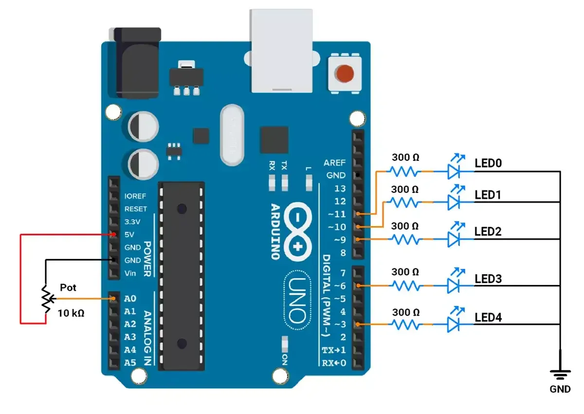
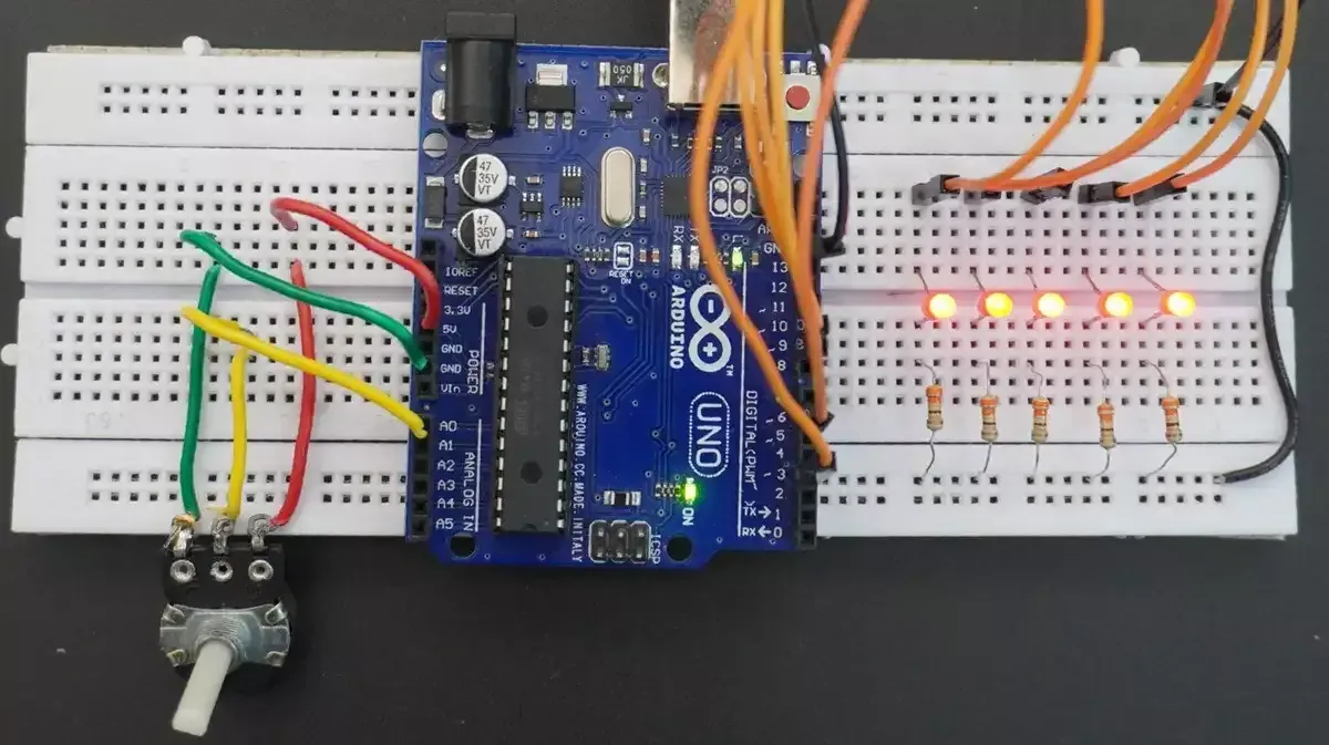
First of all, let's do the hardware connection,
We need to connect the potentiometer to the Arduino ADC. We can use any of the potentiometers with values between 1kΩ and 10kΩ.
Similarly, we can connect the 5 LEDs properly to any 5 PWM pins.
Considering LED drop voltage of ~2 volts and 10mA current.
we can use a resistor with a value,
R = (Vcc - Vled) / I
= (5-2)/0.01
= 300 Ω
Circuit connection

Firmware
After analyzing the task as shown in the GIF.
We observed the following points:
LED Grouping:
- LEDs are divided into two groups:
- Group 1: LEDs with even numbers (LED0, LED2, LED4).
- Group 2: LEDs with odd numbers (LED1, LED3).
- When the Group1 LEDs are fading in, Group2 LEDs will fade out and vice versa.
Fade Timing:
- ADC values (0–1023) are mapped to a delay range (1–10 ms) for PWM control.
- The delay between each PWM step increases as the potentiometer value increases.
- The total duration of the fade-in/out is:
- Minimum duration: 255 ms (255 steps * 1 ms delay).
- Maximum duration: 2550 ms (255 steps * 10 ms delay).
- The fade duration depends on the potentiometer position, changing from 0% to 100%.
Code
const int ledPins[] = {11, 10, 9, 6, 3};  // PWM pins for LEDs
int potValue = 0;	// Variable to store potentiometer reading

void setup() {
  // Set all LED pins as output
  for (int i = 0; i < 5; i++) {
    pinMode(ledPins[i], OUTPUT);  // Configuring LED pins for output
  }
}

void loop() {
  // Read the potentiometer value from A0 (range: 0–1023)
  potValue = analogRead(A0);

  // Map potentiometer value (0–1023) to delay range (1–10 ms)
  // This controls how fast the LEDs fade in and out
  int fadeDelay = map(potValue, 0, 1023, 1, 10);

  // Gradually increase brightness (fade in)
  for (int brightness = 0; brightness <= 255; brightness++) {
    // Adjust the brightness of each LED:
    analogWrite(ledPins[0], brightness);            // LED 0: fade in (brightness increases)
    analogWrite(ledPins[1], 255 - brightness);      // LED 1: fade out (brightness decreases)
    analogWrite(ledPins[2], brightness);            // LED 2: fade in (brightness increases)
    analogWrite(ledPins[3], 255 - brightness);      // LED 3: fade out (brightness decreases)
    analogWrite(ledPins[4], brightness);            // LED 4: fade in (brightness increases)

    delay(fadeDelay);  // Add delay to control the speed of fading
  }

  // Add a delay after the fade-in sequence for proper visibility
  delay(100 * fadeDelay);

  // Gradually decrease brightness (fade out)
  for (int brightness = 255; brightness >= 0; brightness--) {
    // Adjust the brightness of each LED:
    analogWrite(ledPins[0], brightness);          // LED 0: fade out (brightness decreases)
    analogWrite(ledPins[1], 255 - brightness);    // LED 1: fade in (brightness increases)
    analogWrite(ledPins[2], brightness);          // LED 2: fade out (brightness decreases)
    analogWrite(ledPins[3], 255 - brightness);    // LED 3: fade in (brightness increases)
    analogWrite(ledPins[4], brightness);          // LED 4: fade out (brightness decreases)

    delay(fadeDelay);  // Add delay to control the speed of fading
  }
  // Add a delay after the fade-out sequence for proper visibility
  delay(100 * fadeDelay);
}
Code Explanation
- The ADC value from
A0(0–1023) is mapped to a fade delay of 1–10 ms per step. - Fade In: LEDs brighten (
brightness) or dim (255 - brightness) alternately usinganalogWrite()in a loop. - Fade Out: LEDs reverse the pattern in another loop.
- Add delays for smooth transitions and visibility.
Output

Output Video