Editorial Solution
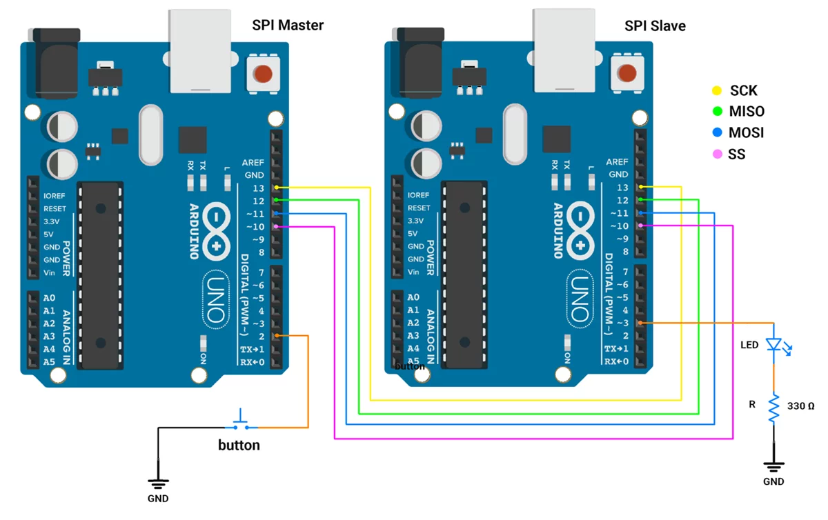
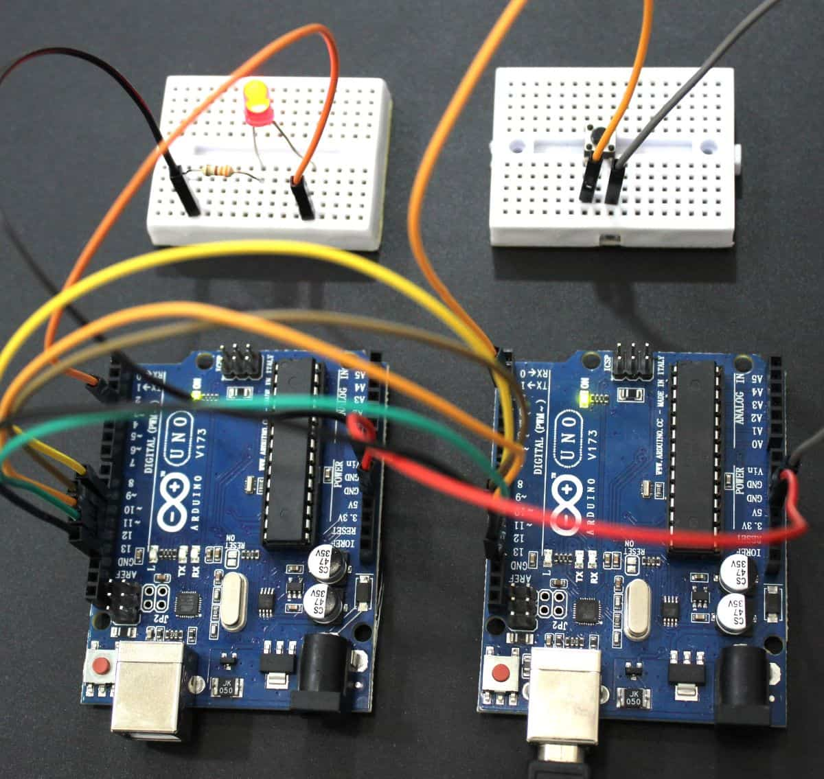
First of all, let's do the hardware connection.
- Master(Arduino UNO)
- Push-Button is connected to any available GPIO pin with an internal pull-up enabled and another terminal to the ground.
- Slave(Arduino UNO)
- LED’s anode is connected to any available GPIO pin and the cathode is connected to the ground via a resistor with a value of 330Ω.
- Master and Slave Connection
- Both communicate with each other via SPI communication, so all SPI pins (MOSI, MISO, SCLK, and SS) of the master are connected to the corresponding SPI pins of the slave.
- And ground should be common.
Circuit Connection

Firmware
- We used two Arduino UNO boards as SPI master and SPI slave.
- We need to develop two separate codes one for master and another for slave.
Master
- Setup: Configures SPI, push button, and SS pin.
- Button Press: Detects valid button presses with debouncing.
- Command Sending: Toggles ledState (ON/OFF) and sends 0x01(ON) or 0x00(OFF) to the slave via SPI.
Code (Master)
#include <SPI.h>

#define SS_PIN 10        // Slave Select pin for SPI
#define SWITCH_PIN 2     // Push button pin

// Variables for button handling
bool ledState = false;           // Tracks the LED state (ON/OFF)

const uint8_t DEBOUNCE_DELAY = 50;    // Debounce delay in milliseconds

// Button state variables
unsigned long lastDebounceTime = 0;   // Last recorded debounce time
uint8_t lastButtonState = HIGH;       // Last stable state of the button
uint8_t buttonState = HIGH;           // Current state of the button

void setup() {
  pinMode(SS_PIN, OUTPUT);            // Set Slave Select (SS) pin as output
  pinMode(SWITCH_PIN, INPUT_PULLUP);  // Set push button pin as input with pull-up resistor

  // Initialize SPI communication
  SPI.begin();                        // Start SPI
  digitalWrite(SS_PIN, HIGH);         // Ensure SS is HIGH (deselect the slave)
}

void loop() {
  // Check if the button is pressed
  if (isButtonPressed()) {
    // Toggle the LED state
    ledState = !ledState;

    // Begin SPI communication with the slave
    digitalWrite(SS_PIN, LOW);        // Pull SS low to select the slave

    if (ledState) {
      SPI.transfer(0x01);             // Send ON command (0x01) to the slave
    } else {
      SPI.transfer(0x00);             // Send OFF command (0x00) to the slave
    }

    digitalWrite(SS_PIN, HIGH);       // Deselect the slave by setting SS high
  }
}

/**
 * Checks if the button is pressed with debouncing.
 *
 * @return true if a valid button press is detected, false otherwise.
 */
bool isButtonPressed() {
  int reading = digitalRead(SWITCH_PIN);

  // If the button state has changed since the last read
  if (reading != lastButtonState) {
    lastDebounceTime = millis(); // Update debounce timer
  }
  lastButtonState = reading;

  // If the button state remains stable for the debounce delay period
  if ((millis() - lastDebounceTime) > DEBOUNCE_DELAY) {
    // If the button state has changed
    if (reading != buttonState) {
      buttonState = reading;

      // Return true if the button is pressed (LOW state)
      if (buttonState == LOW) {
        return true;
      }
    }
  }

  // Return false if no valid press is detected
  return false;
}
Code Explanation(Master)
- Initialization (setup)
- Set up the SPI interface.
- Configures the button (SWITCH_PIN) as input with an internal pull-up resistor.
- Sets the Slave Select (SS_PIN) as an output and ensures it starts in the inactive state (HIGH).
- Main Loop (loop)
- Continuously checks for button presses using the isButtonPressed() function.
- If a valid button press is detected:
- Toggles the ledState variable.
- Sends the corresponding command (0x01 for ON or 0x00 for OFF) to the Slave via SPI.
- Handles the Slave Select (SS_PIN) to manage communication with the Slave.
- Debounce Function (isButtonPressed())
- Reads the button state and verifies stability over a defined debounce period (DEBOUNCE_DELAY).
- Ensures that only valid button presses trigger the LED state toggle.
Slave
- Setup: Configures SPI, LED pin, and interrupt for SPI communication.
- Data Reception: Listens for data from the SPI master using an interrupt.
- Command Processing: When data (0x01 or 0x00) is received, the flag is set to indicate data availability.
- LED Control: In the main loop, the command is processed, and the LED is turned ON (0x01) or OFF (0x00) based on the received data.
Code (Slave)
#include <SPI.h>

#define LED_PIN 3          // LED connected to Pin 3
volatile byte receivedData = 0; // Variable to store received data from SPI
bool flag = 0;                  // Flag to indicate data received

void setup() {
  pinMode(LED_PIN, OUTPUT);      // Set LED pin as output
  digitalWrite(LED_PIN, LOW);    // Ensure LED is OFF initially

  // Configure SPI in slave mode
  pinMode(MISO, OUTPUT);         // Set MISO (Master In Slave Out) as output
  SPCR |= _BV(SPE);              // Enable SPI in slave mode

  // Attach SPI interrupt for data reception
  SPI.attachInterrupt();         // Enable SPI interrupt
}

/**
 * Interrupt Service Routine (ISR) for SPI communication
 * This gets triggered whenever data is received via SPI.
 */
ISR(SPI_STC_vect) {
  receivedData = SPDR;           // Read received data from SPI Data Register
  flag = 1;                      // Set flag to indicate data received
}

void loop() {
  // Check if data has been received
  if (flag) {
    // Control LED based on received data
    if (receivedData == 0x01) {
      digitalWrite(LED_PIN, HIGH); // Turn ON LED if data is 0x01
    } else if (receivedData == 0x00) {
      digitalWrite(LED_PIN, LOW);  // Turn OFF LED if data is 0x00
    }

    flag = 0; // Reset flag after processing the data
  }
}
Code Explanation(Slave)
1. Setup:
- The LED pin is configured as an output, and the LED is turned OFF initially.
- SPI is configured in slave mode, and the MISO pin is set as an output.
- The SPI interrupt is enabled to listen to incoming data.
2. Interrupt Routine:
- When the Master sends data, the ISR reads it from the SPI Data Register (SPDR) and sets the flag to indicate data reception.
3. Main Loop:
- The loop() function continuously checks the flag.
- If the flag is set, it processes the received data to control the LED state and then resets the flag.
Output

Output Video
We can see in the video, that as we click the button on the master the LED connected to the slave is toggling.