Editorial Solution
- I2C (Inter-Integrated Circuit) uses only two wires for communication
- SDA (serial data) wire: Used for data exchange.
- SCL (serial clock) wire: It is a clock signal. Only the master device has control over this SCL line.
.webp)
- The I2C bus has an open drain configuration, meaning it can pull the corresponding signal line low but not drive it high.
- Hence, the line will enter an unknown state. Pull-up resistors need to be connected to the SCL and SDA pins to avoid this.
- We are going to use
Wire.hlibrary for I2C communication which enables the internal pull-up resistor( 20k to 50K ) by default.
Note: While communicating with devices using the I2C communication protocol, pull-up resistors should be used. The value of pull-up resistors may vary depending on the devices used.
- We use 100KHz speed for I2C communication. It is the default speed for Arduino UNO, we can change this speed using
Wire.setClock(frequency);. Maximum frequency is 400KHz for Arduino UNO. - When using an Arduino UNO as a slave, we can set the slave address to any 7-bit value between 0x08 and 0x77. Here we use a 0x08 slave address.
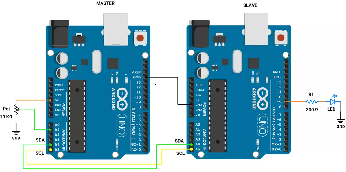
Let's do the hardware connection.
- Master(Arduino UNO)
- The potentiometer is connected to any analog pin of Arduino UNO. The digital output of the potentiometer varies from 0 to 1023.
- Slave(Arduino UNO)
- LED is connected using 330 Ω to ensure safe current flow through it. We can control LED brightness using PWM.
- Master and Slave Connection
- Both communicate with each other via I2C, so the master's I2C pins(SCL, SDA ) are connected to the slave's corresponding I2C pins.
- And ground should be common.
Circuit Diagram

CODE
We need to develop two separate codes one for master and another for slave.
Master Arduino Board Code
#include <Wire.h>

#define potPin A1
#define slaveAddress 0x08  // Slave address

uint16_t brightness;
uint8_t previousvalue;

uint8_t error;

void setup() {
  // Initialize Arduino UNO as I2C master
  Wire.begin();
  Serial.begin(9600);
}

void loop() {

  // It map the potentiometer value(0 to 1023) to PWM value(0 to 255) i.e 1023/255 = ~4
  brightness = analogRead(potPin) / 4;
  if (brightness != previousvalue) {
    Wire.beginTransmission(slaveAddress);
    Wire.write(brightness);                // write data in i2c buffer
    error = Wire.endTransmission();        // send brightness value using i2c
    if (error == 0) {
      Serial.println("Successful data transmission");
    } else {
      Serial.println("ERROR in data transmission");
    }
    previousvalue = brightness;
  }
  delay(10);  // time duration for proper communication
}
Slave Arduino Board Code
#include <Wire.h>

#define slaveAddress 0x08
#define ledPin 9

void setup() {
  // Initialize Arduino as I2C slave (Slave address is 0x08)
  Wire.begin(slaveAddress);
  Wire.onReceive(receiveEvent);  // Attach a function to handle incoming data
  pinMode(ledPin, OUTPUT);
}

void loop() {

}

// Function to handle incoming data
void receiveEvent(int bytes) {
  while (Wire.available()){
  int received = Wire.read();     // Read the incoming byte
  analogWrite(ledPin, received); // Generate PWM signal, to control brightness of LED
}
}
Understand the code
Master Code
- To map a potentiometer value (0 - 1023) to (0-255), we divide the potentiometer value by 4.
Wire.write (); It is used to write potentiometer values mapped between 0 to 255 in I2C buffer.Wire.endTransmission();It transmits the data from the I2C buffer and returns one of the following values:- 0: success.
- 1: data too long to fit in the transmit buffer.
- 2: received NACK on transmit of address.
- 3: received NACK on the transmission of data.
- 4: other error.
- 5: timeout
Slave Code
void receiveEvent(int bytes);It is a callback function that handles the incoming data received from the master. So this function controls the brightness of LED as per potentiometer value using PWM.
OUTPUT
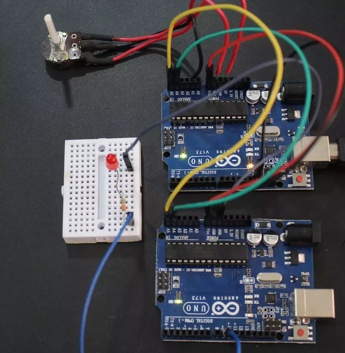
Hardware Setup

Output Video