Editorial Solution
Let’s connect hardware first,
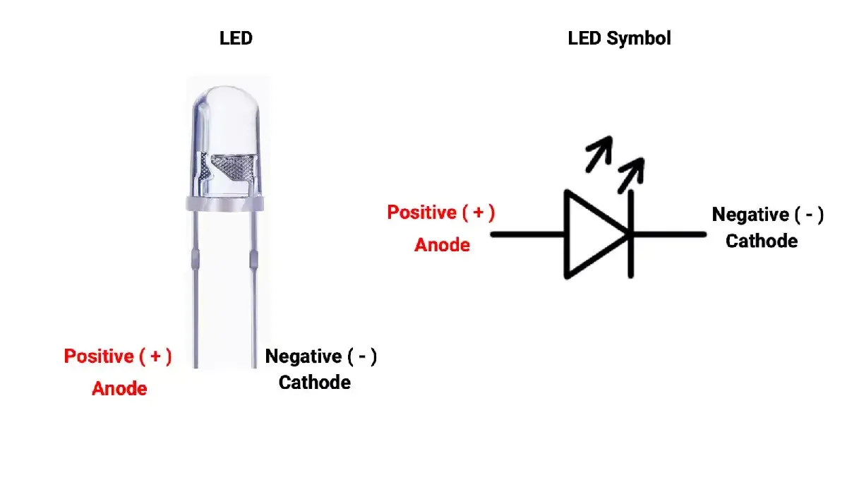
- We need to understand LED terminals properly. As we can see, there are 2 terminals, cathode(-ve) and anode(+ve).
- If we observe properly, inside the LED, there is one terminal, which is flat and bigger in size, which is always a cathode, and the remaining one is anode.
- LEDs need 10 to 20 mA for proper brightness; exceeding this can damage the LED. So, connecting the proper resistor is always important to avoid LED damage.
- The voltage drop is typically around ~2V, depending on the LED color and specifications.
- Always check the LED datasheet for current and voltage specifications.
Note: If the maximum current limit is 25 mA, ensure the current stays below this value. However, due to temperature variations, the absolute maximum current may drop to 20mA or lower. It's important to account for temperature effects and aim to limit the current to around 10-15mA for safety.
Calculating Resistor
- Considering the above points and task requirements, we have to ensure a 10mA current via LED.
- So to Turn the LED ON and OFF, we need to connect it to the GPIO, which we can control via code.
- Arduino GPIO provides around 5 volts when it is HIGH and 0 volts when LOW.
- The LED drop voltage, according to the datasheet, is 1.8v.
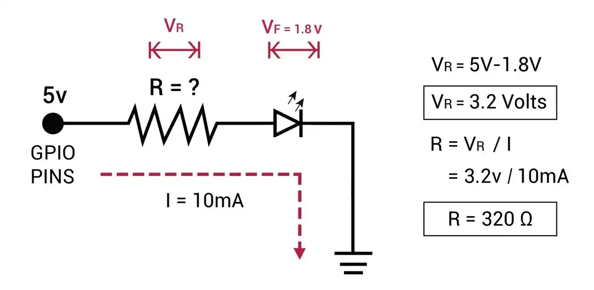
- So we can use a standard value near 320 Ω which is 330Ω or 300Ω.
Method 1: Sourcing Current Through GPIO
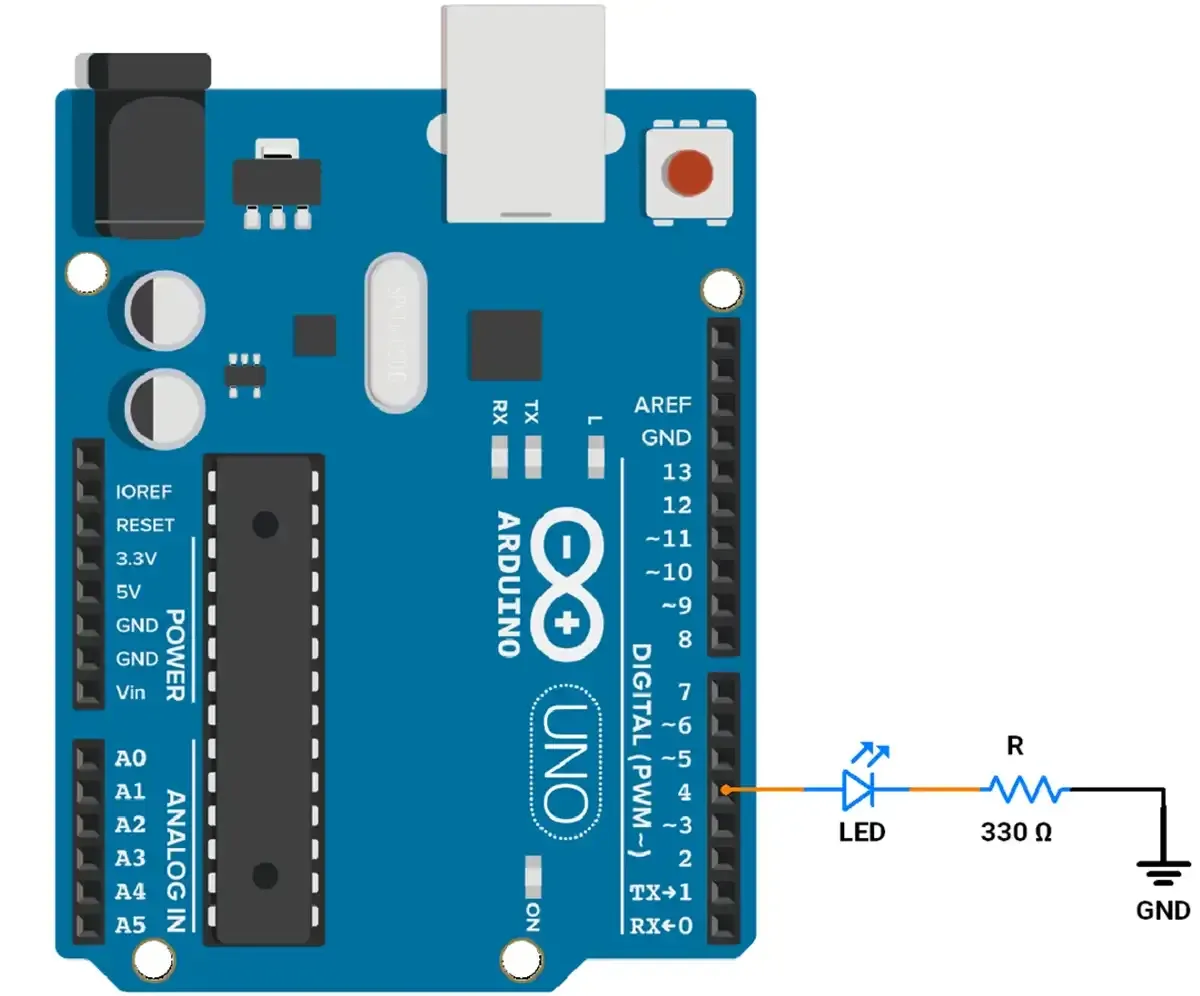
- In this method, current to the LED will be provided via Arduino GPIO.
- So we need to connect the anode of the LED to the GPIO pin, here we will use pin no-4 of the Arduino UNO.
- The cathode terminal is connected to the Ground via the resistor calculated above i.e. 330Ω.
CODE(Source Current)
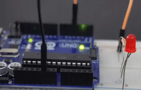
We will turn ON the LED by making digital pin 4 HIGH for 400 msec and OFF by making digital pin 4 LOW for 800 msec continuously.
const int led = 4;          //  LED is connected to the pin 4

void setup() {
 pinMode(led, OUTPUT);          // Set the LED pin as an output
}

void loop() {
  digitalWrite(led, HIGH);        // LED is turn ON
  delay(400);                     // waits for a 400 millisecond
  digitalWrite(led, LOW);         // LED is turn OFF
  delay(800);                     // waits for a 800 millisecond
}
Method 2: Sink Current To GPIO
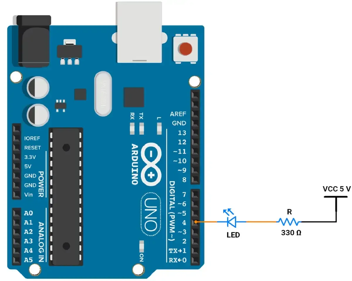
- In this method, current flows to the LED via VCC and sinks through the GPIO pin, which we can consider as GND. When the GPIO pin is LOW, the LED will turn ON.
- Accordingly, we will connect the cathode (-) of the LED to digital pin 4 and the anode (+) of the LED to VCC through a 330Ω resistor.
CODE(Sink Current)
We will turn ON the LED by making digital pin 4 LOW for 400 msec and OFF by making digital pin 4 HIGH for 800 msec continuously.
const int led= 4;                  //  LED connected to pin 4

void setup() {
  pinMode(led, OUTPUT);            // Set the LED pin as an output
}

void loop() {
  digitalWrite(led, LOW);          // LED is turn ON
  delay(400);                      // waits for a 400 millisecond
  digitalWrite(led, HIGH);         // LED is turn OFF
  delay(800);                      // waits for a 800 millisecond
}
Output
Precautions
- We know the source and sink current of GPIO is 40 mA. But practically, we should not exceed the current above 20 mA.
- Also, when we withdraw current through GPIO HIGH, i.e. 5 volts, Its voltage drops with respect to the current withdrawal. i.e.
- For 0 mA, the GPIO voltage is 4.98v.
- For 10 mA, the GPIO voltage is 4.75v.
- For 20 mA, the GPIO voltage is 4.50v.
This shows that GPIO has an internal resistance of 25 ohms.